Application of Anti-Reverse Circuit in Solar System
Source:SolartechDate:2014-07-01
In the actual application process of solar system related equipment, it is inevitable that the positive and negative poles of solar cell components are connected to the equipment by mistake, which may cause more serious consequences. For example, solar controllers such as grid-connected inverters, off-grid inverters and pumping inverters will connect electrolytic capacitors in parallel on the DC input side to support the DC voltage. If the positive and negative poles of the power input are reversed, the electrolytic capacitor will be damaged due to incorrect polarity, causing damage to the controller that cannot be recovered by itself. Therefore, the solar system related equipment is generally designed with anti-reverse connection circuits to ensure that the solar equipment is protected from damage when the input power is reversed.
The simplest anti-reverse circuit is to connect a diode in series with the input circuit, as shown in Figure 1. In applications with lower input voltage, Schottky diodes can be used to reduce the loss due to tube voltage drop. Improve the working efficiency of the whole machine.
Figure 1 Anti-reverse diode circuit
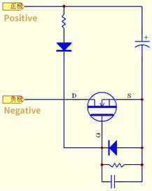
In order to further reduce the loss caused by the voltage drop of the diode, MOSFET can be used as the switching device in the anti-reverse circuit. As shown in Figure 2, select a MOSFET with a small turn-on voltage drop. When the input power is correctly connected , The power supply voltage supplies power to the MOSFET gate through the drive loop, and the MOSFET is turned on; in the case of reverse connection of the input power supply, the difference between the MOSFET gate voltage and the source voltage is negative, the MOSFET is turned off, and the power supply channel is blocked. Choosing a MOSFET device with a smaller on-resistance can significantly reduce the loss caused by the anti-reverse circuit. However, as the voltage level increases, this solution has a lower cost performance compared with the diode solution.
Figure 2 MOSFET anti-reverse circuit
At present, some solar system-related equipment on the market canceled the anti-reverse circuit design, which has a certain basis.Below is the analysis.
The back end of the electrolytic capacitor in the equipment is an inverter circuit, and the IGBT or MOS tube used has an equivalent anti-parallel diode. If the solar power input is reversed, the power will form a short circuit through the anti-parallel diode. According to the characteristics of the solar module, the voltage of the solar power supply When pulled down, the voltage value is only the sum of the forward voltage drop of the two diodes, which will not damage the electrolytic capacitor. The short-circuit current of the solar module is not much different from the rated current. Under reasonable matching, the short-circuit current is short. There will be no damage to the equipment within time.
In order to verify the above analysis, relevant tests were carried out. The maximum output power of the solar array used in the test is 2.2kW, the open circuit voltage is 400V, and the maximum short-circuit current is 7A. The PB2200L pumping inverter produced by Shenzhen Solartech Company was used for reverse connection test. Since the inverter has an anti-reverse connection circuit, the anti-reverse diode in the circuit should be short-circuited with a copper wire. Record the waveforms of the voltage across the electrolytic capacitor and the input current at the moment when the solar array power supply is reversed, as shown in Figure 3. Due to the strongest non-light conditions during the test, the short-circuit current has not reached the maximum short-circuit current value, but it can be measured. It can be seen from the waveform that the voltage across the electrolytic capacitor is clamped to about 1.5V, and the input current is also maintained within the maximum short-circuit current value of the solar array, which is consistent with the theoretical analysis result.
Figure 3 The instantaneous waveform of solar array power input reverse connection
It can be seen from the test that the solar equipment with the anti-reverse connection circuit can indeed ensure its own safety in the case of reverse connection of the solar array power supply. But is it really possible to cancel the anti-reverse connection circuit? We consider the following situations:
1. The power of the solar power supply is much greater than the power of the related equipment, that is, the short-circuit current may be greater than the above-mentioned anti-parallel diode current limit, causing the diode to be damaged by overcurrent;
2. Failure to make corrections in time after the solar power supply is reversely connected, a long-term short circuit will cause damage to the solar array;
3. In the case of parallel input of multiple solar arrays, if one of the solar arrays is abnormal, such as being blocked or damaged, a loop current may be formed between the solar arrays, which will reduce the efficiency of the system, and may damage the solars in severe cases. Components.
The analysis of the first two cases is relatively simple, so I won't repeat them here. For the third case, we conducted related tests. The test used four sets of solar arrays with the same specifications, each with an open circuit voltage of 120V, a maximum output power of 1kW, and a short-circuit current of 10A. During the test, the arrays 3 and 4 are covered with shading cloth, and the working conditions of the solar array are measured and recorded.
Conetion Mode
Solar Array 1
Voltage (V)
Solar Array 2
Voltage (V)
Solar Array 3
Voltage (V)
Solar Array 4
Voltage (V)
loop current between solar Array1/2 & 3/4
Voltage (V)
Open Circuit
115.6
116.2
108.9
108.3
0
4 sets of solar array in parallel
113.6
113.6
113.6
113.6
0.8
It can be seen from the test results that in the absence of an anti-reverse circuit, due to the potential difference between the normal solar array and the shaded solar array, an array loop current will be formed. As recorded in the above table, the loop current is 0.8A, that is, the shaded solar array consumes about 90W of power at this time. If the sunlight conditions are good, the value will be higher, which will cause the battery panel to heat up and affect the service life.
Based on the above analysis and testing, in order to ensure the safety and reliability of the equipment and the solar array under various abnormal conditions, an anti-reverse circuit should be added to the solar system.


 Interested in Solartech

